V5 Chapter 39
Details
222. Twins 2011-02-19
I now have two ICOM IC-R7000 receivers.
The new R7000 is on the top, the old standby on the bottom and off to the right is my YAESU FT-757GX which is a HF ham rig.
This is what I did to the new R7000:
-
Repair of the display
-
Fixed the audio output in the FM mode
-
Completed the alignment for frequency display
-
Disabled the AGC (per item 221 below)
-
Added a DRM module to the 455KHz IF to allow a 20 KHz audio output
I may turn these receivers around on EBay to fund a new receiver that I have been looking at.
221. 2011-02-11 Disable AGC on R7000
For use in Radio Astronomy or SETI the Automatic Gain Control of the receiver must be disabled. This is the procedure used on both the R7000 receivers.
AGC Disable - From Randy Stegemeyer ( hamradio at oz dot net) |
I disabled the AGC on my R-7000 by cutting the top lead of R-115 on the IF board. This resistor is in the base lead to transistor Q18, which is the AGC amplifier. With this resistor opened, no voltage from the AGC rectifier diode D28 can reach Q18 so it never attempts to lower the gain of the receiver. After you take the top cover off, and facing the front of the receiver, R-115 is located about 5 inches from the left side of the receiver, and about 4 inches from the front. Its plainly marked and is standing on end. The lead coming out of the top is easy to clip and easy to solder back if you need to. I never use my R-7000 in AM mode for anything other than radio astronomy so I did not add a switch for turning it on and off, but it would be a simple matter to do so |
I picked up an R7000 receiver on EBay with some known problems. First problem was that the display was not working after a short warm up period. This was fixed by replacing a couple of 10uF caps on the Display board DC-DC converter. Second was a distortion in the audio on FM and FM-W. This was fixed by replacing C135 (5uF) on the IF board.
Now checking the frequency alignment using the steps below - Complete. I can now decide which receiver (or both) to use in SETI Net
I have included these instructions so the the mighty search engines can find them for the next poor soul.
Recovered Troubleshooting Instructions for R7000 and R7100 |
||||||||||||||||||||||||||||||||||||||||||||||||||||||||||||||||||||||
IC-R7000
IC-R7100
|
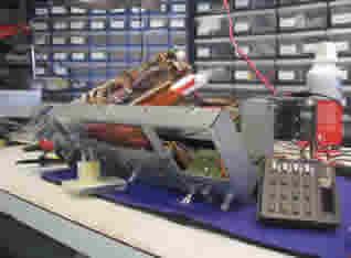
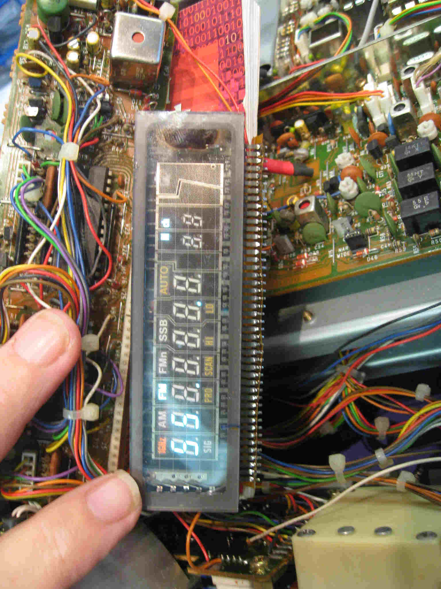
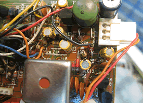
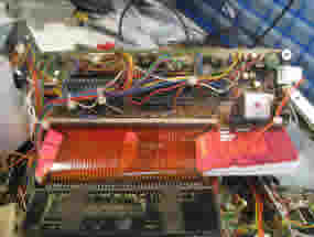
219. 2010-08-15 Receiver Display Problem
I'm having a problem with the frequency display of the main SETI receiver. The ICOM R-7000 receiver uses a EL display for the frequency and other operating parameters. The problem is that the display comes on and works properly for a few seconds and then goes blank. I have the receiver apart and on my work bench (not recommended for the faint of heart) and am now looking at the Display board.
 |
 |
| Receiver Guts | Dead Display |
The main display for the receiver is on the right side. Its a little hard to see from the picture but some of the display works (Mode, and some of the decimal points) but the frequency ELs are out. When I first turn the unit on all the ELs work fine but then crap out. Other than the display the receiver seems to work fine.
  |
|
| Offending Display Board | Top Right Corner where bug lives |
As you can see the Display board is difficult to work on because of the wiring harness and the flex board printed circuit (red in the middle of the picture) the drives the EL display (on the bottom of the picture).
|
| Offending Circuit |
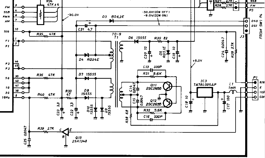
It appears that the little switching power supply made up of Q11, Q12 the T1 starts fine but then changes frequency. Initially is running at about a 5 msec period producing negative going pulses from +6 volts (measured at pin 8 at the bottom on the EL display on the left). This is what I have done so far:
| 1. | Measured out put of IC3 (the three terminal regulator on the right side) | 5 VDC - Good. |
| 2. | Measured the Dimmer switch input (top right) | Schematic shows -30 V off to -9 V on. Measured -26 V, -10 V Close. |
| 3. | Measured the signal coming out of the 1/2 rectifier D5/D6 | Not correct - Should have a 1/2 wave signal to drive the two EL controllers. |
| 4. | Changed both the 10 uF tantalum caps (C20 and C19) | Fixed the problem. |
The electrolytic capacitors in this unit have all reached there end of life so I guess I'll just change all of them when ever I have to open the unit up again.