V3 Chapter 28
Additional Content
157 Laser Pointing System (2008-05-28 to 2008-07-17)
I have received a return on the second Laser I ordered so its time to pull it apart.
.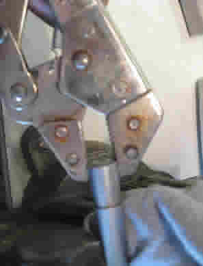
Open Wide - This won't hurt a bit
The Case is +3 VDC and the spring (removed in this picture) is +3 Return. Run a Blk and Red pair as shown. The Wht wire takes the place of the switch - you just pull it to ground
The Laser seems to have a three terminal regulator on board but I decided to simply feed it the 3 VDC as if it came from the pair of AAA's. It draws a minimal 350 mA when running full tilt. I will have to test the current draw on the white wire but I would be surprised if it couldn't be driven by TTL directly.
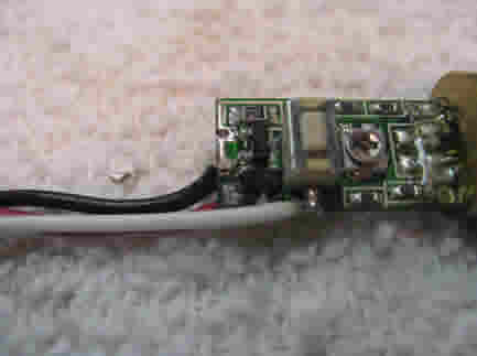
Next I had to pull the button hook (Horn and Head End electronics) down from the dish and figure out where to mount the Laser.
2008-05-31 - Well I have the Head End electronics in my lab and was attempting to figure out how to connect the Laser to the power supply. I measured the current through the switch to ground and it was (surprise) 300 mA so I cannot simply pull it to ground with a TTL output as I had thought. Not only that but I found that the three terminal regulator on the input will blow out at 5 V. So now I have to take the blown regulator off the board and build an off board 3 V regulator to power the thing. I can switch the white wire using the high power capabilities of the Kerr module which is what I had planned to do anyway so that's not a problem.
Live and learn...
2008-06-09 - Life got in the way for a bit but now I have it under control (life that is). I have the Laser installed in the Head End electronics
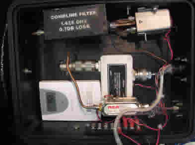
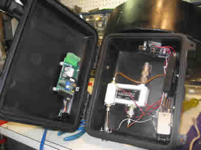
Head End Electronics - Case
The Case half holds the LNA (large white block), the BPF (black block on top) and the BPF relay (gold square on top). The Line Amp going down to the shack in at the bottom. I also put a wireless temperature sensor in the box to make sure the heat rise is not to bad with the Laser running and the BPF pulled in (powered). It looks like it will add 8 degrees over ambient but I'll monitor it for a bit.
This shows the Kerr IO Module
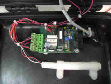
Head End Electronics - Cover
that controls the BPF relay and the Laser. The Laser is Not running in this shot. I have a Plexiglas window I installed to keep the weather out..
I'm now waiting for it to get dark enough to see the Laser beaming out of my antenna.
The Laser beam is very dependant of the ambient temperature. I get a very week beam from it at night.
I'm going to put this part of the project on hold for a while while I work on the Small Radio Telescope.
156 Control of the Band Pass Filter (2008-04-18 to 2008-05-02 )
I have made some 'command' decisions on the cabling of the Head End electronics to the control box.
- Use CAT 5 cable - but two needed to supply the Kerr module control signals and power to the LNA, and Line amplifier.
- Mount the Kerr module on the underside of the Head End box - This will keep the module out of the way of the various hard lines inside the box.
Cabling came together fine. I have it all together and running and back on the air.
Now that I have a Kerr module up in the Head End I have three A/D converters, 15 more IO pins and two high power FET switches that I can take advantage of for what ever reason I can come up with.
155 Test Signal (2008-05-02 to 2008-05-03)
While working with Greg (JO89sn) I realized that I needed a standard WAV file with a known carrier embedded in it for testing. The file had to have a random background noise to simulate what would be heard through the receiver and a single carrier just above that noise level. As a first go at it this is what I have:
Receiver generates random background. I tried the White Noise function of the Tone Generator but I could see many lines in it that were not 'random enough' so I switched to the receiver. The receiver creates a nice Gaussian background noise for the test signal. You can see the typical non-linearity of the DRM module on the jpg and although this is fine for my set up it might not be optimal for others. The receiver was tuned to 1423.056200 MHz with no incoming signal.
Tone Generator generates test carrier. The Tone generator was set to 10,122 Hz. That's as close as I could get it to 10 KHz. the left channel (the one I use) output was set to -24 dB and an additional 10 dB of attenuation from the slider. I did not chirp the signal.
Mixer Combines them. The audio mixer that came with my full duplex audio card was used to mix the two signals
Spectrum Analyzer Displays them. The SETI Net Spectrum Analyzer was started and setup as follows:
- Spectrum Size - 2048 (21.5 Hz/bin)
- 8 mVolt full scale
- Receiver noise set to 1 mV by adjusting the mixer
- Integration set to 4 seconds and allowed to settle
- Test carrier set to 1.2 mV by adjusting the attenuators on the Tone Generator
When this was running right I turned on the Waterfall
Waterfall Detects the carrier. I could see the line developing so I set the threshold to 0.2 (20%) and the waterfall detected the carrier in bin 469. At 21.5 Hz/bin this bin is collecting energy from 10.08 KHz to 10.1 KHz. The bin should have been 470 and why it is off by one I have no idea (could be a count from zero somewhere in the algorithm). I let the system collect three jpgs and one WAV.
These frame jpgs are all much the same 2008-05-02T08-13-09.wav The wave file (24,897 Kbyte) File name is the Data/Time stamp |


This signal should make a good reference to get started.
If this test signal works out I can run it again with Spectrum Analyzer at full resolution (1.2 HZ/Bin) more integration and a lower level test signal.
154 Control of the Band Pass Filter (2008-04-18 to 2008-05-02 )
This task on hold for a few hours while I work on a standard test signal.
Now that the station is up and running again I have to complete the installation of the Band Pass Filter (BPF) control in the Head End electronics. The last version of the station used one of the Control Box to Head End Electronics cable wires to simply switch the BPF in and out. It did that by using one of the I/O pins on the Kerr module that controlled the Az motor. The new version of Kerr modules that I now use do not have this function so I had to find a new control method.
I ordered a Kerr I/O controller that I will place inside the Head End electronics package (up at the prime focus) and when it arrived promptly blew it out. I have a replacement chip set on order now.