V3 Chapter 24
Additional Content
132 ET Detector (2007-03-05 to 2007-03-17)
I now have a running ET Detector running. This is how it works.
The Spectrum Analyzer (below) produces a waterfall display (next picture).
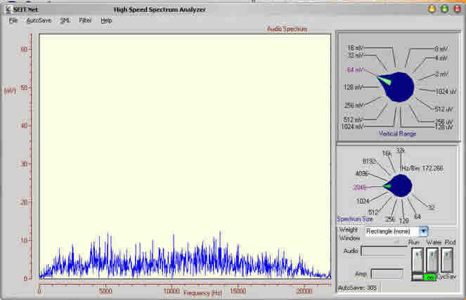
The waterfall converts each display from the Spec Ana into a waterfall where time zero is at the top and audio frequency runs from left to right.
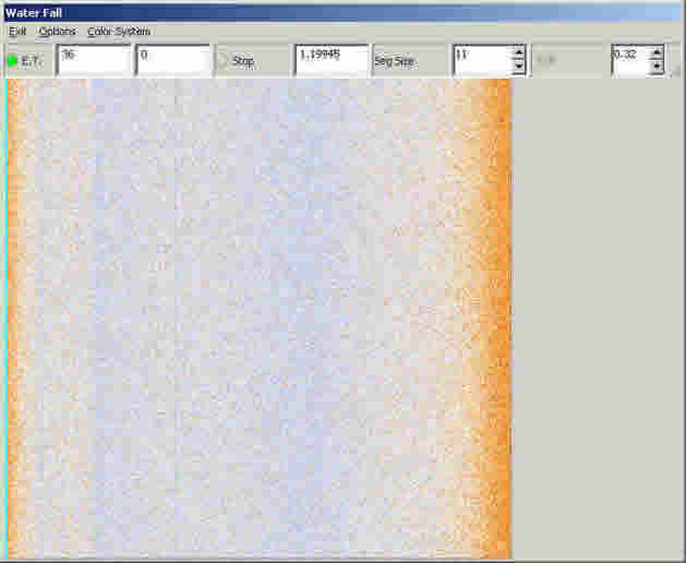
Waterfall
The waterfall does a nice job of displaying signals that are not able to be seen in the Spectrum Analyzer output and it produces many of them (about 1,500 in a short night). The time it takes to produce one waterfall is dependant on the spectrum size and the height of the waterfall image. This one would be created in about 5 seconds. A waterfall from a spectrum size of 16 K would take many minutes.
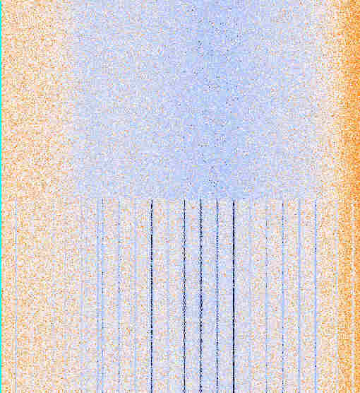
The problem is to 'sound and alarm' when a line, like the one in this waterfall, appear. This is a short description of a working alarm system.
SETI Alarm |
1. Keep a running sum of each bins data:
2. When the last line of the waterfall has been drawn then calculated the average value of each bin.
3. Examine each column average compared to the surrounding averages.
4. Test this value against the column average for the bin under test and a threshold percentage
|
The segment size in effect breaks up the audio response curve into small segments that can be considered flat. If I simply tested the bin under investigation against all the other bins then the lower values on either side of the curve would have disproportionate importance in the calculation. I also added a 30 position graphic equalizer (hardware) in the audio line to flatten out the response as much as possible.
Setting the best segment size is done by trial and error where a spectrum without a signal will produce an acceptably small number of false positives with as low a threshold as possible.
I have found that the best segment size is between 10 and 20 bins and on my system a threshold of 20 to 40% produces a small number of false positives and still detects signals that I can't see by simply glancing at the waterfall.
When the alarm goes of I stop all frequency scanning, lock the antenna on the current DEC and Ra, and start recording the WAVs and jpgs.
The number of false positives is *extremely* important if you don't want if you don't want the ET Alarm to roll you out of bed too many times each night.
131 Image Analysis (2007-02-17 to 2007-03-05)
With the end in sight of the bird hunt and after many thousand of jpg images viewed I have come to a decision that I have been putting off for a very long time. I must face the problem of automatic image classification. Its just to mind numbing to spend three or four hours every morning reviewing the nights collection of jpgs looking for signals.
The principal problem is that the signals that I am looking for are very near the noise level of SETI Net. They are relatively easy to see with the eye but, as you know, the human eye has been trained over eons of time to recognize patterns in noise as a survival skill (is that a leopard hiding under that bush or simple leaves rustling in the breeze? Get it wrong and your lunch) but software is actually very poor at this task.
I have asked several in the community for suggestions on how to proceed and have gotten very few responses from people who should have a solution at hand if there is one.
One suggestion came from the SETI@Home people to look at there open source algorithms for this type of search. I have yet to do this but I will.
Another suggestion came from Earl F. Glynn who has a very good web site (www.efg2.com) that deals in color imaging and problems associated with this discipline. Earl suggested the following:
I’m assuming you’re looking for the vertical “lines” in the images?
My PixelProfile project needs to be updated, but I took a quick look at your data with it:
http://www.efg2.com/Lab/ImageProcessing/PixelProfile.htm
See the attached Word document. You can see the pixel profile right over one of the lines of interest shows different statistics than a “noise” line. My guess is that you could compute statistics vertical line by vertical line – I’d look for a difference in either the mean or standard deviation, perhaps both, trying to find a statistical discriminator. R would be a good tool for statistical analysis, but it’s a bit weak for image processing. There are some packages that would read images into R, but I haven’t used them much.
A “hough transform” can be used to find lines in an image, but I haven’t used them much so I’m not sure how effective that approach might be.
I hope the statistical pixel profile approach might work for you.
This seems like good advice and I have started the looking at his PixelProfile program as a way to start. What a 'hough transform' is and how it works is a mystery to me at this time.
130. Bird List ( 2007-02-12 to 2007-02-22)
This is the completed bird list. It was compiled by scanning the width of my Band Pass Filter (1375 to 1450 mHz) in 15 kHz increments. Each segment was recorded as both a WAV file and a set of jpgs. The jpgs were then reviewed by my high speed line detection hardware (my eyes and brain) for signs of lines. When a line was found it was rescanned by moving the receiver to that frequency and looking again for the signal.
When the signal was found again it is considered a Bird or image or some other local oscillator and its frequency entered in the list. This list will be used to make up a 'No Fly Zone' for the receiver when scanning.
When the signal was NOT found the pointing angles were retrieved from the jpg (using the SETI Net File Manager) and the nearest star selected. This task has no science involved because I only use named stars listed in the Archive section and the star maybe a long way from the indicated antenna pointing location. The files (the jpg and the jpg thumbnail) are then moved to that star entry in the archive for further analysis.
BIRD LIST MOVED TO THE SYSTEM PAGE
129. Sighting Camera ( 2007-02-03 to 2007-02-03)
I decided to install a camera on the horn so that I could see Sirius and verify my pointing angle. I bought a Q-See QSBVC bullet color outdoor camera at Fry's and installed in on the horn. I then re-installed a video switch that was once part of a surveillance suite of cameras and alarms and hooked both cameras to it. It now switches between them once every couple of seconds.
I then looked up the suns position (I use a Navy site) and moved the antenna to that point. I could see that the horn shadow covered the center of the dish so I knew that the dish was pointing correctly. I then switched to the horn view and could see the sun directly. I marked the image on my small TV screen with a bulls eye so I know where Sirius should be when it comes up tonight.
I am also feeding both cameras to this web site, one at a time, so if you see the antenna and next time nothing you know which one is the horn view. We will see how well it works tonight.
128. New LNA BPF Power Supply ( 2007-01-30 to 2007-01-30)
I noticed that the Band Pass Filter (BPF) wasn't pulling in reliably and after looking at the schematic I could see why. I was supplying +15 Volts to the focal point rather than the +20 V I had planned on. I put a new +24 V power supply in the control box and it works much better now.
GPS Carriers
To test the filter I tuned the receiver to the GPS satellites (1575 435 000 Hz) and pointed the antenna to Az 120 El 40 degrees and then switched the filter out half way through the waterfall. As you can see the carriers are reduced to a very low level by the BPF.
127. Line Amp Failure ( 2007-01-27 to 2007-01-28 )
One of the amplifiers in the RF string failed and I didn't catch it until today. Its a simple fix but all the data I had collected for the last two weeks has been with a dead amplifier (no wonder I haven't seen any lines lately). All the WOW data is useless and I will have to start over.
So that this doesn't happen again I am going to use the carrier I detected as a test signal. It produces a nice line (faint but viewable) when the receiver is tuned to:
1406 461 100 Hz AM
This is set as memory channel 2 on the R7000
126. SETI Net Signs of Life ( 2007-01-12 to 2007-01-25 )
After disasters attempts at moving the site through three different web hosting companies It seems to be alright now.
125. SETI Net Dead ( 2007-01-10 to 2007-01-12 )
124. System Status Report ( 2007-01-05 to 2007-01-05 )
I wanted a way that visitors to the SETI Net web site could tell at a glance what was going on. I wanted a status box on the splash page that gave an up to the minute 'box score'. I have it running now and you may have noticed it when you visited last. This is how its done.
You would think that getting dynamic data on a web page would be simple. You may think that but you would be wrong. Its fiendishly complex. All my pages except the first are static. Nothing changes on them unless I fire up Front Page and make the change. When you want dynamic web pages you have a universe of techniques to choose from and they all have one thing in common - they are complex to learn and to implement. I wanted something simple for a single box on one page not a whole new architecture.
The status box is created this way:
- In the Control Panel program, the one that runs the whole SETI Station, the Status module comes to life every 60 seconds and goes out to the other modules for current status. It gets pointing angles from the antenna; frequency from the receiver; operator name from the File Manager and each data item is loaded into a TMemo component .
- When complete it takes each line form the TMemo and converts it a bitmap and stores it in a TImage component
- The TImage is assigned to the Clipboard
- The image in the Clipboard is then converted to a jpg file
- The jpg is sent to the web server using FTP where it replaces the current status jpg file
- The web server is set to refresh its self every few seconds and this causes the new status to appear.
123. Bird List ( 2006-12-30 to Present )
Now that I'm (mostly) past the design/debug stage and into actually collecting data and searching for ET I realize that I will have no problems finding carriers. Every time I turn the system on and collect an hours worth of data 75% of the time I see lines . Right now I'm searching Betelgeuse and the third jpg turned up a nice carrier form somewhere. When I go back and track it down it will probably be a local signal so to keep from searching, and finding, the same bird over and over I have to build an exclusion list. This is as good a place as any to start (Click to view).
Notice that by simply referencing the SML file I get *all* the information that there is for each bird. That's the power of SML.
122. Cable Modem Interference ( 2006-12-29 to Present )
I finally found the source of the carrier at 1420 000 000 Hz. Its been plaguing me for a while and of course its inside my shack all along. This fine, stable, signal generator is my cable modem. I'm connected to Time Warner (Road Runner) and using a Motorola SB4200 Surf Board modem.
Now - what to do about it?
121. Getting Ready for Field Day ( 2006-12-18 to Present )
( I have put this problem on hold for a while )
The software and hardware for SETI Net is now so complex that its easy to loose track of it and if that happens it cannot be depended on if an actual contact situation arises. I need to take stock and see how it would perform in an actual operational mode. Something like this takes place in amateur radio - its called Field Day. Once a year hams that want to participate in Field Day haul there equipment to some field and make contacts with one another and make a contest out of it. The real purpose is to make sure that the equipment will work in an emergency and that the operator can manage the equipment and has not forgotten that all important 'can opener' - you know the one tool that you left on the counter when you pulled out and are now sunk without.
This is how I plan to proceed:
- Create a Field Day Scenario - This will allow me to rehearse the process before it actually happens.
- Trial Assembly - The Entire SETI Net station will be assembled in a slightly different location ( out in my motor home I think).
- Make a list - From these two actions a Good To Go list of equipment and software can be created and used as a check list.
So this is the start.
Scenario -
Hardware Setup - Computer setup and connection to antenna
- The main computer (Zeke) will be setup (wireless keyboard/ mouse, USB powered hub, speakers, two monitors, AC power cord), started and tested.
- The IR7000 receiver will be connected to the Astron power supply (interconnect cable) and to the USB hub and then to Zeke (RS-232 to USB adapter cable).
- Audio output of the receiver will be connected to the Audio Limit Box (RCA to pigtail connector cable) and the output of the Audio Limit Box connect to the Speaker Mike in (four cable part of Audio Limit Box).
- Power on receiver, start SETI Control Panel application and select the Spectrum Analyzer. Verify that noise can be heard and seen. Connect Receiver ('N' Type connector cable to BNC) to the antenna feed. Connect Delphi (laptop in RV) to T-1 feed if available.
Antenna Setup - The main antenna is set to a known operating point
- Select known emitting source and verify operation
Station Software Setup - The File Manager is setup and test recordings completed
- Start the File Manager and load the default SML file (Return to KP-Day 1.xml) as a start.
- Verify the Title Block tab information and add or subtract observers names.
- Verify station Lat/Lon as shown.
- Change to Antenna Tab and verify this setup.
- Enter the DEC/Ra of the first star to be observed.
- Enter the polarization into the Antenna Note area. Mark it 'Polarization - 2' as appropriate..
- Change to the Receiver tab and verify this information.
- Start the R7000 controller and change operating mode. Verify that it changes on the tab. Change the receiver frequency and verify that it is reported correctly.
- Set the receiver frequency to the first channel (1500 - 300 = 1200 mHz).
- Change the SpecAna Spectrum size and verify that it is reported correctly. Set it to 4096 for a 10 Hz/bin collection.
- On the Control Panel set the Stare time to 600 seconds (10 minutes). Set the 'End Stare' to 'Inc Freq' (15,00 Hz) and turn it on. Turn on the chirp. Turn on Refresh.
- Turn on Record and select the area of the hard drive for the recording (Ghost Drive, SETI Data folder). Turn on the Waterfall and verify that is looks right. Verify that jpg's are being created on the SETI Data area. Shut off Recording and erase any jpg's and WAV's created.
- Start Windows Task Manager and minimize it for computer % utilization.
- Request the first star for observation point and request positioning of the antenna.
- Get DEC/Ra and enter into File Manager Antenna tab. Enter the Base Frequency on the Title Block tab on the Notes area.
Normal Operation - Data is collected and the receiver is stepped in frequency or stepping is stopped for ad hoc investigation
- When data is flowing turn on the Record and again verify that jpgs are created. Set the Cycle Saver switch and verify that the jpgs update by frame and that % utilization goes down.
- At the end of 30 minutes (wall clock) look at number of jpgs and WAVs in the collection area. It should be: XX jpgs and YY Wavs.
- Check the Start and End frequencies on the File Manager Receiver tab and verify that they are incrementing.
- For frequency or position change stop the update process and insert new DEC/Ra and new base frequency into the File Manager.
Ad Hoc with Spec Ana - During data collection team scans RF for interesting features
- Using the Spectrum Analyzer, connected to the antenna feed, scan over the 1200 to 1800 mHz band looking for interesting features.
- To move R7000 to a place of interest switch Control Panel Stare Time switch and Chirp switch to OFF. This stops automatic frequency set.
- Spin receiver knob or set new frequency on R7000 control panel.
- Insure that Record is still set and look for carrier with receiver knob. Recording and logging will continue on frequency of R7000.
- For out of spec occurrences (receiver crash, antenna hung, etc.) stop the update process and make an entry into the File Manager note field. This will be saved with the last jpg created.
Ad Hoc with jpgs - During data collection team scans jpgs for interesting features
- Open standard Internet Explorer
- Drag and drop one jpg from collection area to Explorer
- Mouse over image. When expand box appears in lower right click it.
- From then on drag n' drop jpgs looking for carriers. Note any interesting features in the jpgs by writing down the file name.
- Examine a jpg SML by starting a second File Manager (first one is still busy with data collection) and drop a jpg on it. The SML data is displayed in the tabs. Use it to get frequency information and pointing angles.
- To move to frequency indicated in SML switch Control Panel Stare Time and Chirp switches to off then enter frequency into R7000 as before.
- If DEC/Ra changed update that in File Manger Antenna tab.
120. Storage Requirements ( 2006-12-15 to 2006-12-17 )
I am trying to decide how best to use the mass storage for the data I will be generating. This is what I know so far:
|
It seems like there should be more of a difference in the size of the WAV files. I'll look into it.
Answer: My software saves the WAV when it runs out of buffer space which is at 50 Meg regardless of how its collected. WAV files are all sampled at 44,100 16 bit mono so natch they would all be the same size - duh.
119. Antenna Movement ( 2006-12-12 to 2006-12-13 )
The Paraclipse antenna was having a hard time moving through 180 degrees Az. It would start fast and slew toward the goal but then stop short. I found that I had to adjust the velocity constant (AzVelocity = 2000) a lot lower than it had been. This makes the antenna move slower in Az but that's just fine.
The current constants are:
| NumAntModules = 3; // The current number
of Kerr modules on the antenna ElPulsePerDeg = 1531; // Recalculated 2005-04-30. 1. find home. 2.using Kerr move to max, note pulses 3. ElMaxChange / pulses = pulse/deg ElOffsetFromZero = 6; // Measured minimum angle (0 degree wedge) ElPosError = 30000; //12000 ElMaxChange = 35; // Maximim movement from minimum angle from rotor reference was 38 until 2006-07-29 ElPWM = 255; // was 220 Sent to rotor for homing ElVelocity = 100000; // was 101000 ElAcceleration = 100; // was 230 ElKp = 47; // was 30 Default in NMC Test is:100 ElKd = 4100; // was 1000 Default in NMC Test is:1000 ElKi = 50; // was 50 Default in NMC Test is:0 ElIl = 0; ElEl = 14000; ElOl = 255; ElCl = 0; ElSr = 1; ElDc = 0; ElSm = 1; AzPulsePerDeg = 87; // was 91 one 2006-11-11 // Recalibrated setup 2006-03-12 (255 to 90 = 165 deg @ 15,000 pulse for full turn ) AzKp = 59; // Kd Position gain 50 AzKd = 3000; // Kd derivative gain 3000 AzKi = 0; // Ki Integral gain 100 AzIl = 0; AzEl = 14000; // 12000 AzOl = 255; AzCl = 0; AzSr = 10; AzDc = 40; // was 45 AzSm = 1; AzVelocity = 20000; // was 100000 on 2006-12-13, 12000 checked on 2006-06-14 AzAcceleration = 100; //was 90 checked on 2006-06-14 1000 AzPWM = 200; // checked on 2006-06-16 200 AzMaxChange = 165; // Stop to stop checked on 2005-04-26 AzDeadZone = 180 - AzMaxChange; |
118. Remote Client Sky Map Problem ( 2006-12-14 to 2006-12-12 )
While working on the help files for the Remote Client I realized that the Sky Map was being shown as if the antenna were local to the user. Of course it's not - It near San Diego. To make the fix the new client checks its own time zone bias (number of minutes later than UTC) and subtracts that from 480 which is San Diego's bias. The difference is then subtracted from the local UTC and used as the time bases for the Sky Map. It seems to work right now.
117. Control Panel Changes ( 2006-12-12 to 2006-12-14 )
The SETI Net Control Panel integrates all the other applications in SETI Net. It consists of a user interface and links to:
- Spectrum Analyze and Waterfall
- Remote Client
- Sky Map
- Antenna Controller
- Paraclipse Antenna
- R7000 Receiver
- Receiver Controller
- WiNRADiO Controller
- File Manager
Its main job is to perform the search. I determines the start frequency and Ra/DEC and then moves the antenna and receiver to that channel. It then periodically updates the File Manager with pointing angels and frequency etc. It also calculates the receiver chirp and applies it to the receiver.
The current task is to add update capabilities to the File Manager Band Pass Filter settings and the Antenna Lock indicator.
This module is nearing completion and allows more time to be spent observing rather than creating new software.
116. Client Help ( 2006-12-12 to 2006-12-12 )
I am finally getting around to writing a decent Remote Client help.
115. Address Space( 2006-12-06 to 2006-12-12 )
>I made a calculation on the number of ‘channels’ I had to examine on my station. Here are the numbers:
>Since you are all computer literate so you understand the concept of address space.
>If your computer has a gig of main memory and each address of that gig is a byte (8 bits) wide then you have an address space of 1,000,000,000 X 8 bits or 8 Gigabits. SETI Net has its own address space:
- TheParaclipse antenna is 12 foot in diameter. At 1420 MHz this equates to a half power beam width of about 3 degrees (HPBW).
- The antenna can be positioned in declination between -35 and +27degrees. Based on 3 degrees BW this is about 20 positions of DEC.
- This declination band moves past the antenna every 24 hours of RA (360 degrees of earth rotation). At 3 degrees this is 120 positions of RA.
- The Band Pass Filter (BPF) just after the LNA has a pass band from 1375 MHz to 1475 MHz for a total of 100 MHz wide search band.
- The Icom R7000 receiver running with the DRM module has an Audio Band Width of 20,000 Hz (ABW)
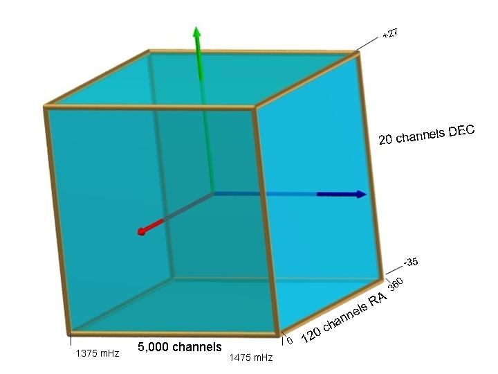
So the address space of SETI Net is:
(BPF/ABW) * (RA/HPBW) * (DEC/HPBW) =
(100 E6 / 20 E3) * (360/3) * (62/3) = 12,000,000 channels to surf (I'd better get started hu).
>I spend 2,000 seconds on each channel so: ~ 2.4E10 seconds or ~ 3,300 years to look ONCE in all my address space