V5 Chapter 40
Details
224. Virtual Audio Cable (again) 2011-03-07
Once more into the breach on this bad boy.
You can download the Virtual Audio Cable here. VAC will work as a free download but the nag is an audio voice inserted in the stream.
The idea is to get two audio streams going to a recording device under Windows 7. In this case one stream is the 20 KHz audio from my SETI receiver (an ICOM 7000) and the other is my Tone Generator application. The recording device is my Spectrum Analyzer (you may download these if you wish).
This is the setup I wish to achieve.

I use the RealTek audio system with the Realtek High Definition Audio Driver version 6.0.1.6299 Finding this driver on the web was a bitch but you can download it. This version contains the all important Realtec mixer.
After installing the Realtek High Definition driver and the Virtual Audio Cable follow the instructions below.
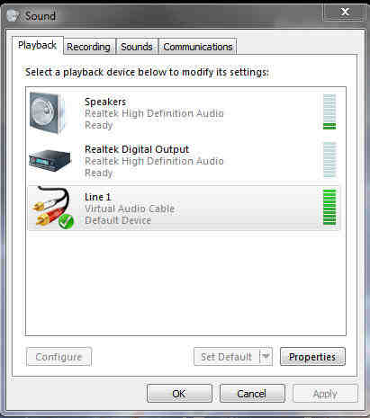
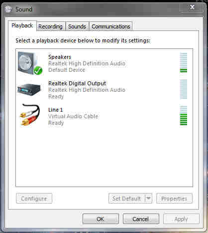
1. Right click on the 'Speaker Icon', select 'Playback' and make sure that Line1 Virtual Audio Cable is selected as the default device. This will change later.
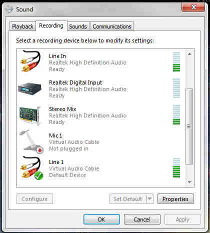
2.Then select 'Recording' and and make sure the Line 1 Virtual Audio Cable is the default recording device.
Please Note: If you don't see the Stereo Mixer under the Recording tab Right Click on any device (like the microphone) and make sure that Show Disabled Devices and Show Disconnected Devices are checked. You may also have to Enable the mixer.
  |
3. OK your way out.
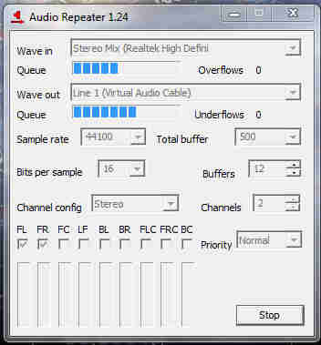
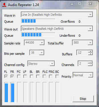
4. Start an Audio Repeater(MME) and set the input to Stereo Mix (Realtek High Defini. Set the output to Line 1 (Virtual Audio Cable). Start a second Repeater and set it up for Line 1 (Virtual Audio Cable) as input and Speakers (Realtek High Definiti as output.
< Please Note: The spelling is correct and will be important later on in these instructions.
| Mixer to VAC | Line In to Speaker | |
 |
 |
5. Right click on the 'Speaker Icon' again and change the Playback default back to Speakers. ( I know, I know but that is what works for me) |
|
6. Start the Tone Generator (or other audio generating application) and the Spectrum Analyzer (or other recording application) and you should see both audio streams.
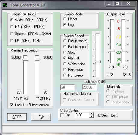 |
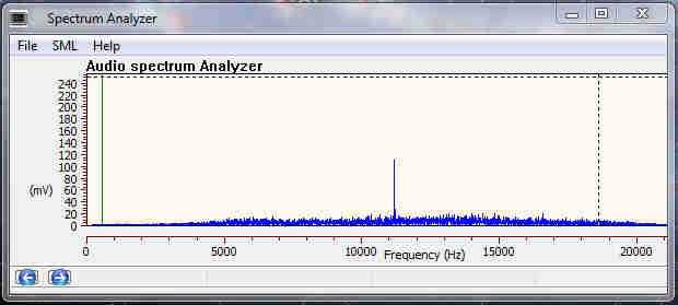
The Tone generator is the signal at 11.211 KHz and the base line is noise from the receiver. |
You should now have two streams running into your recording device. Every time you start your computer these settings should come back and run EXCEPT the Virtual Cable Audio Repeaters. This is how you can make them Auto Start correctly as well.
1. Right click on the shortcut icon for one of the Audio Repeater  and select Properties. You should get this. Select the Shortcut tab.

Change the Target line to Exactly this:
| "C:\Program Files\Virtual Audio Cable\audiorepeater.exe" /Input:"Stereo Mix (Realtek High Defini" /Output:"Line 1 (Virtual Audio Cable)" /AutoStart |
Everything must be like this or it will not work. All the misspellings, all the spaces, all the double quotes - everything.
Hit the Apply button. Now you have a short cut to the Mixer In VAC output repeater set up correctly. Setup the second repeater likewise (make sure of the spelling).
I like to rename the shortcuts to something so that I can remember which is which but it isn't necessary.
2. Next you must get the shortcuts into your Startup directory. Open: "C:\ProgramData\Microsoft\Windows\Start Menu\Programs\Startup" Using Windows Explorer. Drag and drop your two new shortcuts into that directory.
3. Close down you computer, restart, and see if it works.
Good luck
223. Band Pass Filter Check 2011-03-02
I thought I would check the operation of the BPF while I had the test setup A/B switch running.


It seems to be working fine. The Spectrum Analyzer is running at a frequency span of 50 MHz and centered on 1425 MHz. The vertical scale is 10 dB/div. So the bandwidth is about 100 MHz, as it should be, and ranges from 1400 to 1500 MHz.
224. LNA On Order 2011-02-24
I put in an order for a new LNA from Radio Astronomy Supplies (RAS) today. Along the way I managed to meet up, via eMail with my old friends from SARA Jeff Lichtman the owner of RAS. The new LNA, shown below has very good operating parameters.
RAS and WD5AGO present of our "NEW HIGH PERFORMANCE LNA". Our customers/researchers have asked and we deliver! Features include: "LOWEST NOISE FIGURE" of 0.29dB +/- 0.05 dB at 39dB gain., 50 Ohm, Fully machined enclosure, N connectors and external power connector. "Designed and built in the USA". |
1420 MHz. HIGH PERFORMANCE LNA |

This should be in the system by the end of March
223. LNA Trouble 2011-02-20
One of the major reasons for getting and fixing the second R7000 receiver (other than I just like working on stuff like that) was to help figure out why my system was not performing as it used to.
A couple of weeks ago I could tune to 1575,420,000 Hz and point the antenna due east at 60 degrees, shut off the Band Pass Filter, and be sure to see the GPS constellation on my spectrum analyzer. Then I could not. I could see the Weak Signal Source at 1420,385,500 fine but not the GPS birds.
Thinking that it was my receiver going south and wanting a new toy I bought the second R7000 for comparison. After getting it to work to spec I realized that I still could not see the GPS birds.
So I recalculated the focal point of the antenna thinking that it was wrong and had been for a while. It was off a bit and I added some spacers to move it to where it should be. Still could not see the GPS birds.
Now it was getting serious.
So I pulled the Head End Electronics down and removed the LNA. I intended to test each component, one at a time to see what the problem is. I constructed the test setup shown below.
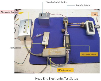
Its a bit hard to see but the Transfer Switch consists of two microwave SPST relays connect to all and A/B comparison arrangement. By pushing the Transfer Switch Control push button the noise source, after being routed through the attenuator, is sent through the LNA and then to the power meter sensor.
This setup showed that the LNA didn't seem to be working. It produced -36.50 dBm when the input attenuator was set to maximum.
To verify what I was seeing I reconnect the LNA as shown in the picture below.
The input to the LNA is terminated with a 50 ohm terminator on a 'N' type connector.
This verified that the LNA was generating its own music at -36.50 dBm. Not a good thing
At this point I asked my good friend (who I have never met in person after all these years) Dr. Paul Shuch, founder of the SETI League, for his input. This is the conversation:
ME |
Dr. Shuch |
|
hope you have time for a dumb question
Paul.
My system has been acting strange for a while so pulled the
Head End electronics down and pulled the LNA (Radio
Astronomy Supplies - 28 dB) out and set it up on my bench.
When I have the LNA input terminated with a good 50 ohm
terminator I get –36 dBm out of the LNA as measured on my HP
Power Meter and 8484 sensor.
I don’t see anything on my spectrum analyzer but it only
goes to 1.5 GHz so it my be oscillating at a higher
frequency. Power supply is solid and quite.
Question – What should I see on a terminated LNA that is
working right?
|
First off, Jim, there are no dumb questions. Dumb
means mute, and since you're asking the question, you're obviously not
that. So, asking a question to which you don't know the answer is not
dumb, but rather, wise.
The output of any properly terminated amplifier is simply broadband noise. The power level of that noise equals the input noise power, amplified by the amplifier's gain. The input noise power is in turn the thermal noise generated by the terminating resistor, added to the internal noise of the amplifier (that is, its Noise Figure or Noise Factor). So, let's calculate: As a first order approximation, let's consider the amplifier's noise figure to be near zero. That is, its internally generated noise is negligible -- it is a Low Noise amplifier, after all. So, all we have to do now is calculate the noise generated by your dummy load resistor. (Note that, in this context, dumb is appropriate...) Let's consider that load resistor to be a thermal black body. Planck's Law says its noise power (in watts) equals kTB. In this equation, k is Planck's Constant (6.6 x 10^-34 kg m^2/sec). T is the physical temperature of the black body, in Kelvins (for lab temperature, you can assume 300K). And B is the bandwidth in which the noise power is being measured. Now, since you're measuring noise with an HP 8484 power sensor, whose passband is 10 MHz to 18 GHz, you might assume the bandwidth B to use in this calculation to be about 18 GHz. But, remember that the power sensor is going to be placed at the output of an amplifier with a much more modest bandwidth. Thus, the only part of the load resistor's noise power that counts is that part within the LNA's passband. Let's say your LNA passes frequencies from 1.3 to 1.7 GHz. That's a 400 MHz bandwidth, which is what we'll use for B in Planck's Equation. OK, let's calculate. Noise power Pn (coming out of the
load resistor, in the amplifier's passband) is kTb Pn = kTBConverting to logarithmic measure, that's a power level of -240 dBm. This is the noise power that gets amplified by your LNA. Your LNA has 28 dB of gain, so the -240 dBm of noise, after being amplified, comes out of the amplifier at a level of -212 dBm. OK, now the noise you're seeing on the power meter is -36 dBm, which is a whopping 176 dB stronger than the noise you should be seeing. From this, I conclude that, yes, your amplifier must be oscillating. How's that for a long answer to a simple question? My main point is, the noise power coming out of a properly operating amplifier is entirely calculable (and, now, you know how to calculate it). Vy 73,Paul Prof. H. Paul Shuch |
At this point I have to decide wither to buy a new LNA or attempt to fix this one (tough job). Stay tuned.
Just for the heck of it I rendered Dr. Shuch's output in Mathematica and added a couple of other things.
LNA NoiseWhat to expect from a terminated LNAThe output of any properly terminated amplifier is simply broadband noise. The power level of that noise equals the input noise power, amplified by the amplifier's gain. The input noise power is in turn the thermal noise generated by the terminating resistor, added to the internal noise of the amplifier (that is, its Noise Figure or Noise Factor). So, let's calculate Noise contributed by dummy load As a first order approximation, let's consider the amplifier's noise figure to be near zero. That is, its internally generated noise is negligible -- it is a Low Noise amplifier, after all. So, all we have to do now is calculate the noise generated by your dummy load resistor. Dummy load as Black BodyLet's consider that load resistor to be a thermal black body. Planck's Law says its noise power (in watts) equals kTB. In this equation, k is Planck's Constant (). T is the physical temperature of the black body, in Kelvins (for lab temperature, you can assume 300K). And B is the bandwidth in which the noise power is being measured. This is what the Black Body curves look like at various temperatures In[134]:= Out[135]= Out[136]= Bandwidth of LNANow, since you're measuring noise with an HP 8484 power sensor, whose passband is 10 MHz to 18 GHz, you might assume the bandwidth B to use in this calculation to be about 18 GHz. But, remember that the power sensor is going to be placed at the output of an amplifier with a much more modest bandwidth. Thus, the only part of the load resistor's noise power that counts is that part within the LNA's passband. Let's say your LNA passes frequencies from 1.3 to 1.7 GHz. That's a 400 MHz bandwidth, which is what we'll use for B in Planck's Equation OK, let's calculate. Noise power Pn (coming out of the load resistor, in the amplifier's passband) is kTb In[137]:= Out[141]= Out[142]= Converting to logarithmic measure, that's a power level of ≈240 dBm. This is the noise power that gets amplified by your LNA. ConclusionYour LNA has 28 dB of gain, so the -240 dBm of noise, after being amplified, comes out of the amplifier at a level of -212 dBm In[145]:= Out[146]= |