V4 Chapter 30
Details
Noise Source being tested
171. 2008-09-27 Back to Software
Now that the antenna moves I need to make a basic decision. Here is the problem:
I'm about an ace away from building a new user interface with 100% to Delphi. The only thing that is stopping me right now is a simple reed switch on each of the motors. As you may remember the Java code counts the reed closures and computes the position from that and then commands the motor to the next position.
The trouble is that the hardware OR's the reeds from the two motors and therefore can only move one motor at a time. So the antenna has to do a Up/Left, Up/left, Up/left to move itself. That isn't so bad but there is no way to command the antenna to 'give up' its current position - you simply have to send it a count and hope it counts reed blips correctly. The end result of this is that every time you start the application the rotors have to go to the stow position and start over. I hate that.
I can change it by adding a second reed switch to each motor. Then I can feed the reeds to my Kerr motor controllers, rather than the one that came with the system, and they remember where they are. Since I have a controller for each motor I can slew in both Az and El at the same time. I love that.
The problem with that is that after I get the antenna running with the new controllers it will no longer work with the original hardware and Java software. I will have to recreate the functions of the system, in Delphi, without really understanding them from experience with the Java version.
So as usual I between a rock and a hard place (been there before) and am not really sure how to proceed. I think I'll tough it out with the Java version for a while and see what I can learn but its really tempting to chuck it all.
170. 2008-09-22 Controller Problem
I now have the head end electronics installed and have tested the radio (works) and the rotors (work). The problem is that the ground control box doesn't seem to want to move the motors (I tested them with a bench supply). I did make a mistake during the initial testing with the control box and may have blown up the 'H' bridges. They are LMD18200's and the box has three of them. I ordered five samples from National Semiconductor just in case but tomorrow I'll start troubleshooting the box.
I got the controller fixed.
It turned out that the 9 pin circular connector was not mating correctly with the cable connector going to the antenna. I could not find a replacement connector and got tired of screwing with it so I did the following:
While I was working on the terminal strip I found a cold solder joint on the PC board inside and that may have actually been the problem. The terminal strip may not look as nice as the circular connector but it will give me less trouble.
169. 2008-09-21 Coming On Line
After finally getting the fourth LNA support pole together with the other three I was able to attach it to the dish. This was done by rotating the Elevation 180° and then the Azimuth 180°. This brings the top to the bottom where I can get to the mounting screws. It also proves that the rotors move the way they should.
Next task is to find a way to mount the LNA to the four support poles. I think I'll attach it first the way is was manufactured and get the receiver running to set a base line. Then I'll find a way to make a universal mounting fixture that will accept either the SRT horn and receiver or the SETI net horn, LNA and filter. This will allow me to swap electronics between SETI and Radio Telescope operation.
Going - going <gone>
168. 2008-09-15 Good By Paraclipse
If you have been watching the development of SETI Net you know that one of the biggest problems I have had is with the antenna rotor. Since the SRT rotor seems to work well I have decided to remove the Paraclipse 12' antenna and rotor and replace them with the SRT rotors and antenna. This decision was not taken lightly. The Paraclipse and its rotor all the electronics and the software was working perfectly and this only has happened a few times in the twenty year lifetime of the dish. But out with the old and in with the new.
Comparing the SRT rotors to the 20 year old Japanese robot positioner is like comparing a Porsche and a John Deer (SRT Rotor being the tractor). The Japanese Porsche/Rotor is all contained in a form fitting case with four or five needle bearings, Hi-Tek flex circuit cabling between the motors and over all look of a well designed machine. The SRT/Deer rotor looks like it was welded together on a lunch hour break by the guys in the back of Economy Auto Wrecking. I don't think there is one bearing in the thing.
On the other hand the John Deer rotor motors can be worked on without removing the rotor from the pole. The rotor can be removed in two parts (Az and El) and the antenna itself is about 1/2 the weight of the Paraclipse. Sometimes you need a John Deer when you just want to plow a furrow.
If you look at the pictures above you can see the deconstruction of 20 year old friend (foe) the Paraclipse antenna.
167. 2008-09-12 SRT Mount Problems
I finally had time to bring the Az and El antenna mounts into my shop and open them up.
- The Elevation mount was tested first. I connected my bench power supply directly to the motor and - nothing. It turned out the the motor has three wires on it White, Black and Green. By convention the Green wire is *always* case ground but not on this system - its hot and Black is case ground. The Motor seem to work alright but draws 0.8 Amp with no load.
- I applied power to the Azimuth motor (36 VDC @ 4 amp) and it does move. It draws 1.3 Amp.
- Both Az and El position is detected by counting pulses on a reed switch mounted on the motor case. Its a single phase system, rather than the two phase system that I use and it is mounted after the first set of gears so the resolution is not as accurate.
- The Az mount is capable of 180° of movement only. This is a mechanical limitation and there is no fix for it. But wait. The Elevation mount is also capable of 180° movement but it is mounted vertically so the pair can cover the entre sky - Sweet.
Next step is to connect both motors to the Ground Control box and see what happens.
I plan to write client/server software so that the system will be able to be used over the internet by anyone. Eventually the system will be moved to TDS but it will be at my house for the time being.
2008-09-01 SRT DISH
I made the decision to replace, temporally, the SETI Net Paraclipse antenna with the SRT antenna from the club mountain top site (TDS). It became apparent that to build a fully operational remote radio telescope was not going to happen unless I could have all the hardware to work with. This means that I will be suspending any SETI searches for a while while I work on the hardware and software.
166. 2008-08-30 The SUN
Today I managed to make a raster scan of the Sun. It takes about 5 minutes to collect one block of the sky (20° Azimuth and 20° of Elevation). The process is fully automated but is still very rough.
| One Block of the SRT Sky | ||||||||||||||||||||||
| 0 | 21 | |||||||||||||||||||||
| 0 | 0 | 174 | 168 | 166 | 170 | 173 | 171 | 170 | 168 | 166 | 167 | 166 | 171 | 176 | 180 | 179 | 179 | 181 | 177 | 176 | 177 | |
| 168 | 173 | 170 | 170 | 175 | 176 | 171 | 169 | 175 | 175 | 174 | 174 | 173 | 171 | 174 | 173 | 170 | 172 | 173 | 172 | 170 | ||
| 166 | 171 | 168 | 172 | 172 | 176 | 170 | 176 | 174 | 172 | 176 | 174 | 177 | 175 | 177 | 176 | 175 | 175 | 171 | 173 | 169 | ||
| 170 | 168 | 174 | 175 | 182 | 180 | 177 | 180 | 179 | 177 | 178 | 176 | 179 | 167 | 172 | 172 | 173 | 169 | 171 | 174 | 168 | ||
| 173 | 172 | 169 | 174 | 174 | 176 | 171 | 174 | 176 | 173 | 178 | 177 | 182 | 178 | 180 | 176 | 185 | 176 | 183 | 178 | 173 | ||
| 171 | 171 | 176 | 177 | 179 | 174 | 179 | 183 | 197 | 198 | 201 | 199 | 180 | 179 | 168 | 175 | 176 | 174 | 176 | 178 | 176 | ||
| 170 | 174 | 179 | 181 | 179 | 180 | 175 | 177 | 207 | 233 | 291 | 298 | 293 | 276 | 216 | 201 | 183 | 176 | 172 | 174 | 173 | ||
| 168 | 174 | 169 | 172 | 177 | 193 | 262 | 306 | 440 | 496 | 522 | 468 | 356 | 290 | 199 | 181 | 178 | 183 | 182 | 182 | 173 | ||
| 166 | 174 | 181 | 182 | 180 | 177 | 209 | 243 | 413 | 541 | 761 | 806 | 770 | 684 | 462 | 349 | 211 | 187 | 177 | 174 | 176 | ||
| 167 | 178 | 178 | 178 | 197 | 232 | 384 | 522 | 800 | 935 | 964 | 909 | 627 | 498 | 282 | 218 | 182 | 181 | 180 | 183 | 179 | ||
| 166 | 180 | 176 | 182 | 181 | 184 | 232 | 276 | 487 | 623 | 861 | 924 | 858 | 757 | 492 | 367 | 236 | 210 | 192 | 185 | 180 | ||
| 171 | 183 | 193 | 200 | 207 | 230 | 315 | 384 | 575 | 647 | 688 | 625 | 458 | 372 | 247 | 213 | 184 | 181 | 179 | 181 | 182 | ||
| 176 | 179 | 180 | 179 | 184 | 181 | 192 | 213 | 256 | 310 | 384 | 423 | 398 | 352 | 268 | 241 | 213 | 207 | 202 | 190 | 187 | ||
| 180 | 186 | 188 | 194 | 193 | 192 | 197 | 209 | 226 | 240 | 247 | 234 | 207 | 199 | 187 | 183 | 178 | 181 | 184 | 182 | 180 | ||
| 179 | 180 | 181 | 185 | 181 | 179 | 181 | 180 | 180 | 183 | 180 | 184 | 183 | 180 | 177 | 182 | 179 | 185 | 190 | 182 | 184 | ||
| 179 | 179 | 179 | 178 | 175 | 174 | 175 | 175 | 173 | 169 | 175 | 171 | 173 | 175 | 176 | 175 | 177 | 179 | 177 | 181 | 177 | ||
| 181 | 175 | 176 | 178 | 176 | 181 | 177 | 171 | 172 | 171 | 170 | 171 | 173 | 172 | 173 | 171 | 172 | 173 | 171 | 177 | 174 | ||
| 177 | 173 | 172 | 174 | 171 | 174 | 177 | 174 | 170 | 176 | 172 | 174 | 175 | 171 | 176 | 173 | 176 | 177 | 181 | 171 | 171 | ||
| 176 | 174 | 173 | 169 | 174 | 173 | 178 | 171 | 170 | 170 | 171 | 170 | 171 | 177 | 177 | 181 | 178 | 178 | 177 | 174 | 177 | ||
| 177 | 177 | 171 | 174 | 176 | 173 | 174 | 179 | 174 | 174 | 173 | 172 | 174 | 170 | 172 | 172 | 174 | 167 | 174 | 170 | 169 | ||
| 174 | 168 | 166 | 170 | 173 | 171 | 170 | 168 | 166 | 167 | 166 | 171 | 176 | 180 | 179 | 179 | 181 | 177 | 176 | 177 | 174 | ||
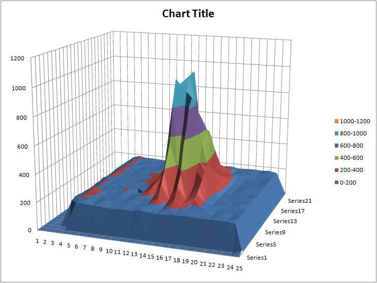
This is the resulting Excel chart of the scan array (above). You can see the antenna side lobes on the front of the image (the green and purple series) and a nice sharp peak in the data.
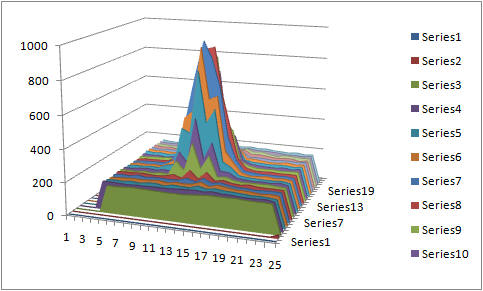
The SUN in raster scan
There are lots of problems with the software and hardware but this chart gives me some hope.
If you are an Excel wizard download the chart and create a better image. I would love to post it and give you attribution.
Second (and last) Sun shot of the day. No science here but you have to admit - damn that's a pretty picture...
Creation of the Scans |
A Radio Telescope is really a thermometer. Its measures the energy of the photons that reach it from whatever source and it produces readings in kelvin (at least it will when I manage to get it calibrated). The resolution of the ‘scope is directly related to the size of the dish and the frequency used. It’s calculated using the relationship shown on my web site at: http://www.seti.net/html/SETINet/OtherInformation/Calculators/calculators.htm For a 12’ dish running at 1420 mHz the resolution is about 3 ° of Half Power Beam Width. That means if the dish is pointed directly at the Sun and then moved off three degrees that signal will drop in half (3 dB). So you can see that there is no way to improve on this 3 degree resolution other than by increasing the operating frequency or the size of the dish. The scans I did were done like this: I then fire up Excel and create the chart. Steps 2 through 5 are all automatic and take about 10 minutes to complete. The resulting picture shows several things. The gain is calculated as a power ratio between the baseline and the peak. The second thing is the antenna side lobes. These can be seen clearly on the first chart as the green and purple set of three peaks. On a well calibrated and aligned antenna the side lobes will be minimal – these are not. They are like a fringe you see on a star image when the telescope is not collimated correctly. |
164. 2008-08-30 Finding the Focal Point
Finally achieved a decent peak on the sun. This is the run down:
| Reading | Elevation | Azimuth | Reading | Distance |
| 1 | 48.6 | 118 | 200 | 63.75 |
| 2 | 48 | 119 | 265 | 61.5 |
| 3 | 50 | 121 | 513 | 59.00 |
| 4 | 52 | 126 | 750 | 57.50 |
| 5 | 59 | 129 | 770 | 54.75 |
| 6 | 60 | 131 | 1020 | 53.00 |
| 7 | 60 | 133 | 830 | 52.00 |
| 8 | 62 | 140 | 1050 | 53.25 |
Used my SRT data collection tool running at 500 mSec and the attenuator in line. Control of the antenna was from my Paraclipse control program version 2.2
This is the procedure:
- Created a sun position chart from the U.S. Naval Observatory http://aa.usno.navy.mil/data/docs/AltAz.php - This gives sun position in Az/El in 10 minute increments
- Home the dish
- Move the antenna to the first sun position and find the peak
- Record the data. Distance is from the center plate of the dish to the lip of the C-Band feed
- Slide the horn in an inch or as close to that as possible.
- Go to step 1.
It looks like reading number 6 was close to the peak so I set the horn a little bit longer (53 1/4 inch) and locked it down. Why the peak so 53.5 and not 60.5 as calculated - I haven't a clue.
I will re-run the chart this afternoon when the sun comes down into my elevation range (about 3 pm).
163. 2008-08-20 First Light + 1
No light/No joy yesterday so now what.
Last night with the horn & receiver back on my bench I was able to see the noise source as expected. I found that you have to hold the noise source about six inches from the horn and orient the dipole to be parallel with the 1420 MHz probe but it does seem to work.
The two pictures below are of a software test module collecting data from the receiver and of the noise source oriented about 6 inches from the probe. The probe is difficult to see but its at 11 o' clock inside the center ring of the horn.
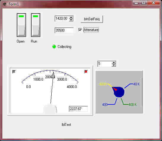
With 6 mA running into the noise source I get about 2400 on the meter. With the noise source shut off I get about 1600 on the meter. With the probe rotated 90 degrees I get about 2400 on the meter with or without power to the noise source. Rodolfo Montez U. of Texas measured 108 K in his paper on the Noise Calibrator so this un-calibrated change of 800 seems to be in the ball park.
Back To Basics
So the receiver does seem to be working. That leaves the possibility that I did not have it mounted at the focal point of the antenna.
The focal length F is given by:
F= D²/16z
D is the diameter of the dish and z is the depth of the dish.
Next is to measure the diameter and depth of the dish to make sure I know what they are. I'll use a piece of wire stretched across the dish for the measurement. This is actually not an easy measurement to make because my dish is mounted and is 12' across. Reaching in to make the depth measurement will be a challenge.
By pulling a wire as tight as I could make it from one spreader to an opposite spreader I measured 146" in diameter. By pushing a tape measure through the hole in the center of the back of the dish and up to the same wire I measure 22" of depth.
This makes F = 146²/16*22 or 60.5" I don't think this is where the horn was yesterday.
162. 2008-08-18 First Light
Enough of the system works so that today is the day to try to gather our first set of photons. I have decided to mount the receiver on a spare button hook for my Paraclipse antenna and use my antenna positioning software to move the antenna and the SRT application to collect data from the receiver. It aught to be exciting...
Well - No Joy. Something is amiss. I cannot see any difference in power reading when I sweep the sun. I am getting data back from the receiver.
Work'n it boss.
161. 2008-08-17 Software testing
After thrashing myself half to death on Java I finally got a working system. This is what I had to do:
- Recruit a Java expert - Jon Petrescu, also a member of SDAA stepped up to the plate
- Install NetBeans - NB is a clean development environment for Java applications and is a lot like Delphi so, with Jon's help, I was able to get it started. Jon and I use the Microsoft Windows Live Messenger to communicate with each other during the day.
- Download H180 - We were using the wrong version of this software for a while but after we downloaded the correct Java files from MIT's web site we were able to start communicating. The H180 designator is the type of antenna mount we have.
- Switch to RxTx -The serial interface module used in the original Java code is woefully out of date. Jon suggested we switch to the RxTx package and after a bit of tweaking it came on line.
- Learn the SRT User Interface - This is a 'painful' piece of software. I was written about eight years ago in Java and shows its age. Its alright to use to get the thing under control but *must* be replaced to be usable.
- Delphi test application - While I was learning Java I needed to keep my sanity with a small Delphi module that connects to the receiver and displays the resulting data.
There are still many things going on in the Java interface but its starting to work.
160. 2008-07-23 Software startup - I have the Receiver and the Computer Interface in my lab for testing. What I don't have is the dish and the positioning rotors. For the test I have to open the software and disable the rotor commands and to do this I have to bring myself up to speed in Java.
I have downloaded the Java development environment from SUN Microsystems and have it installed on my computer. Now I have to learn Java. Luckily Java and Delphi (my native langue) are similar so it won't be like starting from scratch but it will be a challenge. I'm running some 'Java for Boys and Girls' programs now.
As they say - Stay Tuned...
