V3 Chapter 27
2006-06-16 to 2006-08-12. Recalibration of the antenna Lock-To-Lock logic, addition of counter weights, Work on the status page (stalled), purchase of a spectrum analyzer and O'Scope, Construction of a audio front end device and Client/Server nears completion.
Additional Content
153 Ready to Fire It Up (2008-04-04 to Present)
It looks like I'll be running again this morning. I wont have control over the band pass filter in the head end electronics and the antenna will be at the lowest elevation range but it will be on the air.
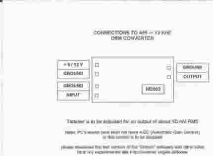
152 DRM Module Hookup (2008-04-03 to 2008-04-04)
John G0GCL ask about the connections for the DRM converter board in the SETI Net Forum.
Hope this helps John.
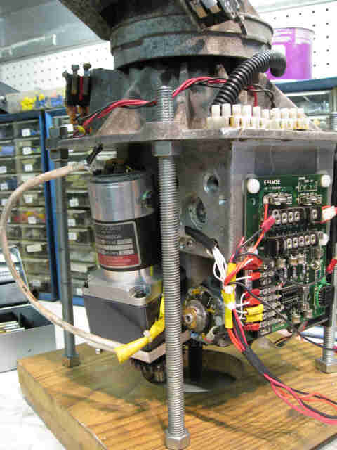
| 151 But Wait - Not Dead Yet (2008-01-18 to 2008-04-01) I found a
motor at a local suplus store that may work. I can shoehorn it into the case and
it seems to be strong enough. It has a 100:1 gear case and is bulker than
the last El motor. Its rated at 27 VDC 2 A operating.
Notice the 'tilt' on the motor? This is necessary for the gears to mesh and for the top of the motor to fit within the case. I had to whittle out a new yoke from 1/4 inch aluminum plate to mount the motor on. I have also installed a Hall effect sensor on the tope of the motor (you can see the mating Hall effect on the Az motor just to the right of the test jig threaded rod) and am now wiring it together. Might still work.
|
2008-03-15 Seems to work now - This is a YouTube video of the operation under manual control
2008-02-17 I am still rebuilding both the control box and the rotor interface. I found that I was having a lot of 'cross talk' between the motors and the opposite position encoder so that when one motor would be commanded to stop the other would take off and drive into a mechanical stop. Not a good thing. I have chucked the rotor interface board (shown above) and replaced it with a simple set of terminal blocks. I am also replacing all the cables with shielded wire. This should clear up the cross talk problem.
2008-01-26 I decided to rework the control box while I was at it. The original used plastic circular connectors on it the leaked and allowed corrosion. I am replacing that with terminal blocks and shielded cables for the motors and sensors. Some in process pix are below:
 Control Box Thumbnail. Click for full size
The control box will have a terminal strip (right side of pix) to carry the motor power up to the rotor and Az/El position data and limit switch information back to the control box. I have moved to RJ-45 connectors to link down to the control computer (white square on left side bottom) and up to the head end electronics (top white square). The terminal strip will eliminate the water problem I had with the old circular connectors and the RJ-45's will allow me to standardize on Cat 5 cables and connectors.
 Jack
of Control Box Thumbnail. Click for full size
Jack
of Control Box Thumbnail. Click for full size
This pix shows the twin H-Bridge controllers for the motor control via the computer and the manual switch controls along the bottom. The middle switch switches between manual and remote.
I decided to build everything on the cover of the box rather than mounting the H-Bridge controller in the box and the switches on the cover. This will allow me to remove the cover only and have all the electronics in hand to work on in my lab.
I also decided to move the third controller card, the PIC I/O, up to the head end electronics. This will allow me to control the filter In/Out relay close to the relay itself and to take advantage of the other functions on the controller. One of these is an A/D converter that I could monitor the temperature or possibly a diode detector for a full total power system some day.
2008-01-23 While working on the motor I managed to break the Hall Effect sensor on the new motor. I tried to get a new sensor all over the area but have found out that now days the sensor and the op amp are combined into a three terminal device. I did manage to extract a sensor board, with the newer three terminal devices on it from one of my other motors and it fit on top of the new motor like it was designed for it. So now I can go back to wiring the rotor together.
2008-01-22 Hall Effect device needed. I have managed to blow out the device that supplies Phase B from the motor. Its the one marked HA in the picture below. Does anyone have one of these little beasts in there parts box?

The (reverse engineered) circuit is below
150 Rotor Dead Again (2008-01-08 to 2008-01-18) Within minutes of getting the last bug out of the software (got the I/O module working) the elevation motor twisted its self in half. I am afraid that this is really the end. I have tried seven or eight times to repair the rotor always with a bad outcome. The bottom line is that unless I buy a new one I am out of the SETI business.
Id like to say 'Stay Tuned' but in this case I don't think there is much point.
149 Clean Up (2008-01-07 to 2008-01-08) - Control of the comb filter in
the head end electronics needs to be reestablished. After the last YARR I
had a lot of trouble with the RS-485 communications bus and decided that one of
the problems was that I was using an out of date Kerr module to control the
filter relay. I ordered and received a new module, 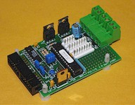 The PIC - I/O General Purpose I/O Controller. This module is really
overkill for what I need (single TTL output that drives a relay) but what the
heck it has a lot of neat stuff on it that I might find a use for. It has:
The PIC - I/O General Purpose I/O Controller. This module is really
overkill for what I need (single TTL output that drives a relay) but what the
heck it has a lot of neat stuff on it that I might find a use for. It has:
|
I may want to hook the analog channel to the power supplies to monitor voltage/current or I may want to put a temperature sensor on it.
I always create a new MultiSIM schematic for any new module like this so that I can work with it so this is the next step.
148 Clean Up (2008-01-06 to 2008-01-08) - Now that I have the antenna running (again) some things need to be cleaned up. First is the small matter of when I move the antenna up the indicator in the control panel moves down. This happens because the motor is turning backwards from what I expected and changes almost every time I change motors or gear cases. On the schematic below the DIP 16 jumper is corrected to get the correct Phase A and Phase B down to the electronics from the Elevation Encoder. I use National Instruments MultiSIMversion 9 for my electronic design now. I gave up on OrCAD because it was just to hard (not complex) to use. The OrCAD user interface is a throw back to DOS and shows it.
That fixed the reverse motor problem.
