V3 Chapter 22
105. Raising the Paraclipse ( 2006-11-08 to 2006-11-09)
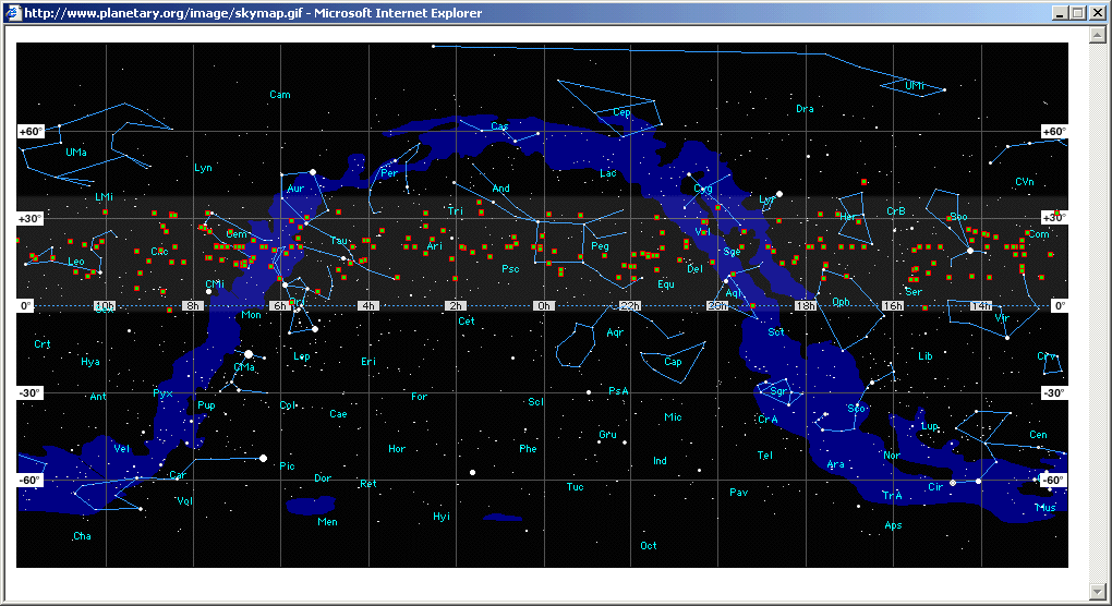
The SETI Net hardware and software seems to be stable enough that I can spend more time observing rather than fixing and inventing. We will see how long this lasts but the first thing is to decide where to look. I was looking at the Planetary Societies web site at the report on the Reobservations made by SETI@Home on the Arecibo receiver. They also have an image, below, of the 'hits' recorded by the system. As you notice most of these are between 0 and +30 DEC because of the location and orientation of the Arecibo dish.
 SETI@Home 'Hits'
I have decided that I will select two or three of these hits and concentrate on them for a while. To view at least some of the same sky as Arecibo I have to raise the Paraclipse to its maximum elevation. This is done by removing two 1/2 inch stainless steel bolts and swinging the antenna up to a new set point. To do this I had to remove the 70 lbs of weight I had in the counterweight system, attach a block and tackle and pull the antenna up, then re-insert the two bolts.
The two pictures below show the before (below) and after changes in the search area. Notice that the two bottom pictures don't look the same as the one from the Planetary Society? Its because I took the original and cut and pasted it to move zero hours RA to the right side rather than in the middle of the screen.

Additional 15 degrees of elevation

Original minimum elevation
A quick swing from Az min to Az max and the antenna crashed into the corner of the house. The extra 15 degrees created a interference with the house and the antenna. What to do? Move the antenna over? Go back to the minimum elevation? Nah - cut the corner of the roof off. I got out my trusty circular saw and cut a notch about two inches on a side into the roof corner This allows the antenna to move through it OK.
Now I can go about the business of selecting one or two of the hits for further viewing.
104. Frequency Correction ( 2006-10-26 to 2006-11-08)
I am currently using a Digital Radio Mondiale (DRM) module connected to the Icom IC-R7000 receiver. This module takes the receiver 455 kHz IF and shifts it down to the 12 kHz band. This gives me approximately 18 kHz of usable audio bandwidth that I can send to the SpecAna rather than the 3 kHz bandwidth I could get if I simply digitized the audio output of the receiver.
This approach works well and results in a smooth, flat audio signal that I can use. The thumbnail below shows the SpecAna with a 18 kHz audio signal from the receiver

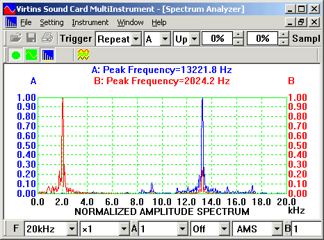
The problem is that the DRM module also shifts the apparent signal frequency by 12 kHz. The screen shot below shows the output of the receiver, in SSB mode, from the audio jack (red) and the DRM module (blue) using the dual channel Virtins spectrum analyzer. As you can see the receiver frequency 'appears' to be shifted up by 12 kHz. This is not a large problem except that I log the receiver frequency directly with the data, using SML, so if I report a signal at say 1420 384 400 Hz it actually would have been at 1420 396 500 Hz.
To counteract this effect I will simply subtract 12000 from the frequency reported by the receiver.

Tested and works well.
BTW you can order one of these sweet little modules from: http://xoomer.alice.it/i5xww/Home.html

455 kHz to 12 kHz down converter.
103. Filter Control Problem ( 2006-10-22 to 2006-10-26)
During normal station operation I had a failure (broken wire in the limit switch) and during the fix I decided to replace the two Kerr control modules with two new ones that I had on hand. These are Servo -SC types and are a bit different. After replacing them I found that the Elevation control no longer worked. Much bug tracking later I found that the filter control bit on the El control module was not working. A few emails to the inventor of the modules Jeffery Kerr lead me to understand that the new modules can't control external devices and attempting to do so was causing the failure.
Now I have to find a different way to control the RF Band Pass Filter relay. I could put one of the old version modules in the LNA/Filter box and run the RS-485 but up to it. That might be interesting.
102. SETI Markup Language (SML) ( 2006-10-10 to 2006-10-22 )
2006-10-22 I have revised SML to show two child elements under Equipment Setup - Antenna and Receiver. These elements will make it simpler to manage the schema. I have also removed the element Data and folded the pointing angles into Antenna element and receiver frequency into the Receiver element. This is a much cleaner arrangement. I will post the complete syntax and semantics it settles down a bit.
SML needs to be revisited. The original idea was to automatically create a file that contained the SML tags AND the data set. The focus shifted to automatically creating a file that contained the WAV data with the SML buried inside. To accommodate this change in thinking the SML element Data_Set has been removed. To further clarify this new architecture the Equipment_Setup element now has two children - Antenna and Receiver and the essential tags moved from the old Data_Set element to these new elements.
I am now in the process of juggling the SML syntax (using XML Spy) and SML Generator code to accommodate it.
