V2 Chapter 19
Start of the new year resolution list, bug in the ICOM R 7100 notch filter, New Kerr modules installed, Antenna power supply redo, search for new antenna rotor and work on the client/server software.
Additional Content
81. Client/Server Software ( 2006-05-11 to 2006-06-15 )
I need an Alpha tester to help me. That person will work with me on shaking out the bugs in the SETI Net client/server software. Requirements are:
- Willingness to work without pay - consider it a hobby, I do
- Able to devote a couple of hours/week for several weeks any time during the day or night is fine. If you are outside of the U.S. that works as well.
- High speed connection to make the process as painless as possible.
- Some knowledge of antennas, receivers and SETI. I am not looking for and expert in any of these fields only someone with a grasp of the basics so that, together, we can smooth out the client/server software and hardware.
The Alpha tester selected will download the current Client software and simply run it on his computer. When something doesn't run right or is not understandable email the SETI Net mail list with the specifics. I will make the changes and post a new release. We will use the mail list so that other users can view the process and comment on it as we go. Its as simple as that.
If you think you are the one for this task post on the SETI Net Mail list. I will set up a Master Client account for you and we will get started.
Release version 2.0 of the client now posted. Sky map seems to be working well now.
2006-05-21 Designing out loud - I am attempting to design the software that will control the antenna position graphically - the Sky Map. It has been in the Remote Client software for a while but has never worked correctly. This is what Antenna and Sky Map need to do on each refresh time tick..
Antenna Refresh Process
Each tick the Antenna Refresh Process will
- Call Sky Map Refresh. This will keep the Sky Map icons current with the antenna hardware. This call is done first to keep the icons on the screen with minimum update blink.
- Redraw the Sky Map icons (Star location, Ant location and Scan area)
- Update the Sky Map Current Ant Position parameters
- Check for a New Ant Position signal from Sky Map. When sensed the Antenna will use the parameters to command the antenna movement. That will move the antenna to the new position. This operation only for the current Master Client.
Sky Map Refresh Process
Scan Switch= Off - This is the initial condition.
- The search area is displayed, the Lock Led is off, Lock parameter is reset
- Antenna Finder click shows the current position of the antenna. Sky Map uses Current Ant Position parameters for this purpose. Star Finder click shows the current location of the star icon. it is at an unknown position on initial use or last position after that.
- Current Ant Position parameters are used to move the Ant icon
- Sky Map Mouse left click moves the antenna to the clicked on location. This is done when Sky Map sets its New Ant Position flag and parameters. The Antenna senses the New Ant Position flag, resets it, and uses the New Ant Position Az/El to change the needle positions on the Az and El gauges. This starts the physical antenna moving. At each refresh Antenna will update the Sky Map Current Ant Position Az/El values.
- Mouse right click moves the star icon to the clicked on location. This is done by Sky Map alone since Antenna does not know shit about stars, Lock conditions or the Scan switch.
Scan Switch = On
- The star icon position will be tested to be within the antenna scan area. If not an error message will be displayed and the Scan switch will be shut off. The operator will have to right click within the scan area, which moves the star icon, and set the switch again..
- The Antenna position icon will start moving toward star icon. This is done because Sky Map first senses that Current Ant Position is outside current star position, by more than one degree in any direction, and sets the New Ant Position flag and parameters to the star location. The Antenna will sense the new position flag and use it to set the needles on the Az and El gauges. The Lock LED will change to Money Green color
- When Current Ant Position and Star position are within 2.5 degrees (in Az and El) of each other Sky Map will set Lock parameter and Lock Led will change to Lime color.
- When Scanning is attempted on a star position outside of the range of movement of the antenna (the search area) the system will make an audio report using the Windows Question sound. The operator can stop this report by shutting down the scan operation or by selecting a new star within the search area.
2006-05-18 Still working on changes to the Client/Server software. I now have the 3kH/18kH switch sorted out but ran into a lot of other issues that have to be worked off one at a time. Stay tuned.
I will be running some test on the software for further changes. One of the first things will be the addition of a switch on the front panel of the client receiver to select between 3 kHz and 18 kHz audio stream.
I also need to build a better set of audio cables between the Icom receiver and the sound board on the remote server.
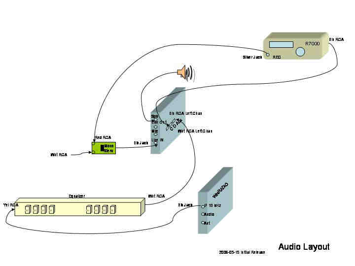 jpg of the Sound Layout for SETI Net
80. Rotor Replacement Search ( 2006-04-27 to 2006-05-11)
2006-05-11 Rotor repaired again. I found a broken connection in the Az position encoder electronics and once fixed the system seems to work.
2006-04-29 - The antenna and rotor is coming down from the pole (see the picture on the front page). I did get a quote from EGIS but is was 1,200 EURO for the rotor alone. That is way to much so I am looking for a used version or some other solution.
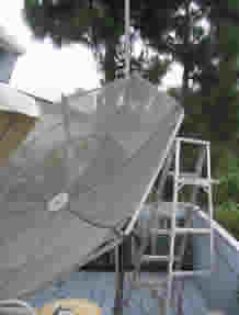
Antenna Down for Rotor Repairs
I got the antenna and rotor down once again with only a few minor scratches (to me not the antenna) and have the rotor down in the shop for work. The front picture shows the Jin pole still up and ready for replacement of the rotor and antenna. It looks bent because the camera is twisted a bit.
The main rotor is old, broken (again) and needs to be replaced. Its been on the pole for nearly 20 years now and has suffered much - I cannot keep it running any longer. A long Google session turned up a company in Germany, EGIS that sells the same rotor with a modern design. I am in contact with them to see if a replacement can be purchased.

Rotor Repair Underway
79. Remote Server Streaming Audio (2006-04-08 to 2006-04-27)
I now have the basic part of the streaming software running and am working it into the Remote SETI Server software. Stay tuned.
Working on the audio streaming software for the Remote SETI System. This is turning out to be more difficult than I thought.
78. Rotor Power Supply (2006-03-02 to 2006-04-08)
I have the antenna running again and now am casting about for the
next direction to take. Rather than use any of the commercial supplies that I found I
decided to build one myself. This is a +36, +16 + 5 Volt system to run the
rotor motors and associated logic. 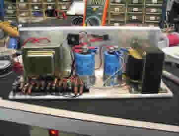
I managed to get the power supply installed and running but not without blowing out my two new Kerr modules (damn). Just as I was installing the last module I dropped a test probe across the 110 VAC coming into the control box with predictable results (lightning flash, swearing, *really* bad smell, etc). I have new chips on the way but managed to get two of the older modules running in the mean time.
The power supply seems to work better than the old switching system I had before with the added advantage that I can repair it when it blows out.
2006-03-02 I received the two modules from Jeffrey Kerr and installed them without problem. Along the way I realized that my 24 VDC switcher power supply, for the elevation rotor motor, was folding back to about 10 VDC when asked to move the dish. This accounts for the slow elevation movement that I have noticed lately. The fix is to replace the power supply. I don't know about you but I find that switcher power supplies are a pain. They are always crapping out. It's not that they are electrically noisy, that problem seems to have been designed out with proper shielding and grounding, it's simply that they fail way to often. I am going to move to simple linear regulated supplies. I found and bought several power supplies from a local surplus house today and will attempt to find a combination that will run the rotor. Stay tuned.
77. RS-232 Network (2006-03-01 to Present)
I have been having a problem with the antenna control system. It has two of these modules , one for Az the other for El. They both hang from an RS-485 bus and turn on the rotor motor when commanded from the control computer and count motor revolutions and report back the change in degrees.
Lately they have been throwing off checksum errors for no reason the I can figure out. I have brought them both down to the shop and hooked them to a local RS-485 bus and they do error out once in a while. I have 'scoped them till I'm blue in the face and cannot seem to find the problem. When they work - they work well; when they fail the fail miserably.
I gave up and ordered two new controllers form Jeffrey Kerr, LLC yesterday
with a two day delivery. 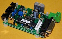
The
new modules are a different design but should work for my system. I
also ordered a stoc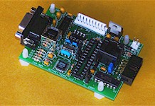 k RS-232 to RS-485 converter to eliminate that as a possible
problem child. Hopefully this will clear up the instability of the
rotor servos.
k RS-232 to RS-485 converter to eliminate that as a possible
problem child. Hopefully this will clear up the instability of the
rotor servos.
Stay tuned.
76. ICOM IC R7000 Problem (2006-02-03 to 2006-02-20)
Now that the receiver is back running I can go ahead with other problems. I found a few new bugs in the R7000 driver software and released them. I moved the antenna control software away from an OLE architecture and to a simple Delphi unit. This is mostly complete and is released. Now its back to the Client/Server stuff (from the To Do list below). Currently I am working on the audio stream again. The server side is still un-incorporated into the server application and should be for consistency and startup flow.
76. ICOM IC R7000 Problem (2006-01-10 to 2006-02-02)
Don Latham from the SETI League pointed out that C135 could be leaking and would slowly bias up the op amp. I have simply broken out the cap and will replace it from the top so that I don't have to remove the IF board itself. Stay Tuned.
- Well that didn't help. My choices are now to either take the circuit out of the system or replace the op amp. I guess I'll look for a op amp first. That can be changed from the top by busting the old one out and soldering to the legs that remain. I found a couple of these at Fry's for a buck each...
- Damn - didn't help either. I had to finally pull the IF board out and install a new Op Amp after busting out a perfectly good one, but the problem remains. Now that I know that the Op Amp and the input cap (C135) are good I 'should' be able to track down where the bias voltage is coming from. There are only three caps in the schematic that could account for it and I nominate C138 that 0.01uf lurker is the only way DC could get to the input of the amplifier. We will see.
- Double Damn - that didn't help either. With that cap out of the circuit it acts the same. I guess I'll just have to drive it to its logical extreme by removing the next cap in order. C137 - your out of there!
- Triple Damn - I have removed *all* the caps and still no change.
- I connected C135 directly to the output and the thing seems to work. This cuts the filter right out of the circuit. This shows a deep misunderstanding of the intended operation of that filter circuit on my part. Does anyone have a better suggestion?
2006-01-17 - A problem has crept into my receiver (ICOM R7000). What happens is that in SSB mode the audio will die off. It will restore itself as soon as I power off and then back on but after about 3 min. it dies again.
I have tracked the problem down to a notch filter on the IF board. The schematic is below. I find that if I simply touch pin 5 on the op amp the circuit will start operating correctly but then will die again after about 3 min. I cannot figure out why that should be. I could replace the Op Amp but its hard to get to and I'm afraid that I might cause more problems getting to it. I have simply heated the pins on the op amp with my iron but that didn't help either. One thing that bothers me is the fact the amp has +8.9V on the positive rail but -7 on the lower rail. I'm not sure if this could be the problem or a red herring.
Any help? eMail Me: Thanks.......
75. New Years To Do List (2006-01-01 to 2006-01-10)
I love the start of each new year. It allows me to ignore the failures of the past and plunge into the next year with the erroneous idea that everything is going to turn out great. I always start with a to do list.
| Module | TO DO Description | Status |
| Remote Client | This software needs work. It was developed over a
period of time when learning the ins and outs of Client/Server development
was the principal goal - it shows.
|
I will update this area as I work off the TO DO List
|
| Remote Server | This module is a jumble of various building blocks, some of
which are actually separate EXE's and it needs to be regulated.
|
|
| Antenna Server | I managed to figure out how to turn off the driver error
message boxes that were locking up everything but now the fun starts (this
may be the biggest problem in this list).
|
|
| Spectrum Analyzer | It turns out that the SpecAna will be a key component for
Remote SETI as well as for the local SETI Net station. It is where the
incoming signal is converted to the frequency domain and where the waterfall
is generated. It also is how the WAV file is tagged with SML and
archived. It need attention.
|
No progress on any of these |
| Second Antenna | Right now there is only one antenna available. I need
a second, reference, antenna for the lower band (100 to 200 mHz) and I have
a 5/8 dipole available to use it.
|
I have the vertical mounted and the cable run to the shack. No movement on the switching relay yet. |
| Help System | Configuring this station is a nightmare. I need
something 'like' a script setup that can help a remote user get on board and
for my self as well. I also need a web centered help page for remote
users.
|
No progress on any of these |
| Archive System | I have the basics of a data archive system on the web site
now but it never has worked right. This could be an important part of
the Remote SETI and well as local SETI station operation.
|
No progress on any of these |
| New Receivers | I still have two more receivers that could be brought into
SETI Net Yaesu FT-757 HF receiver/transmitter and the Yaesu FT9000 UHF
receiver/scanner
|
No progress on any of these |
